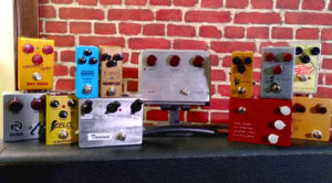
Klon or Klones? A legend under the lens
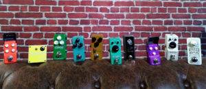
Few pedals exist out there whose legendary status and hype have peaked as high as that of Klon’s Centaur overdrive. This pedal, worth a couple

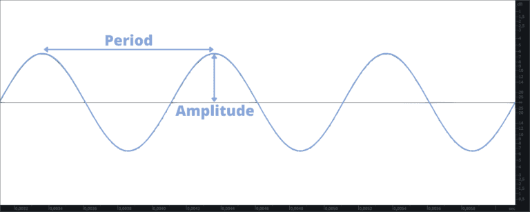

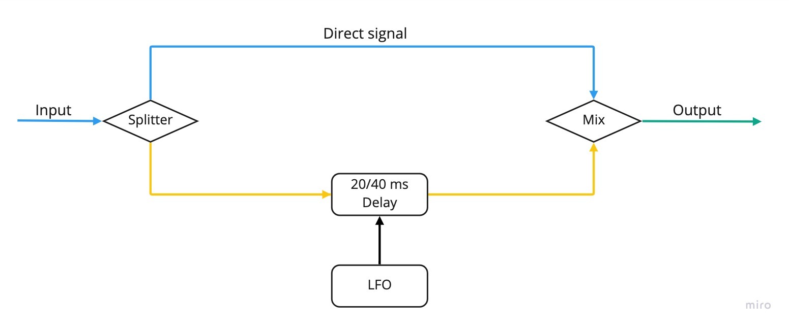
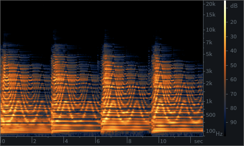
Finally, we come to the one concept that we can use to explain all secrets behind modulation pedals: that of the phase of a wave.
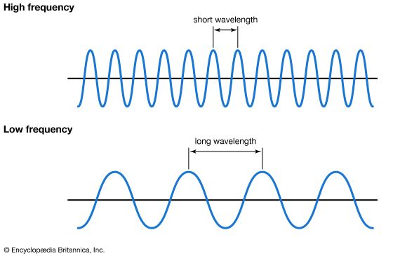
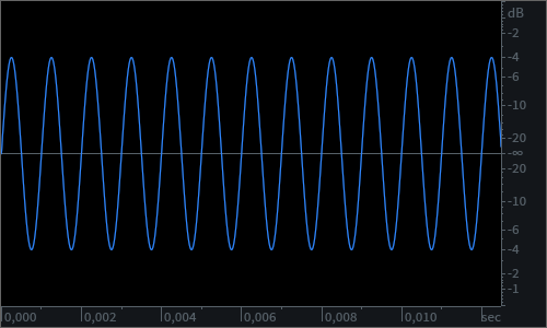
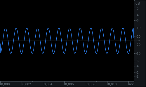
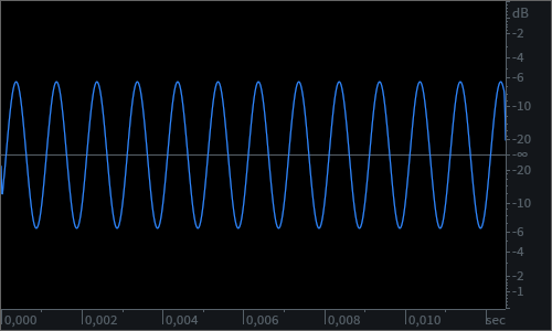
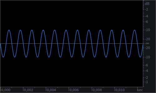
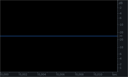
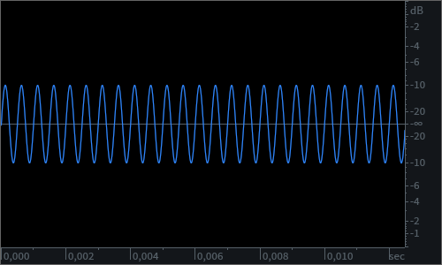
To make things clearer, we will use sine waves for our examples. Sine waves are created by a single frequency, linearly going from neutral state to their peak and then trough and back to neutral. In this case, how “steep” the wave appears, and how quickly it performs its cycle, is only influenced by its frequency.
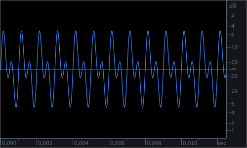
Phase is a concept used to describe the location or timing of a point in a wave cycle, usually expressed as degrees of an angle that is measured in that literal cycle. For example, the crest point of a sine wave is 90° of its cycle, and the trough is its opposite, 270°. The moment that phase becomes really important, however, is when two waves interact with each other.


Klon or Klones? A legend under the lens
Few pedals exist out there whose legendary status and hype have peaked as high as that of Klon’s Centaur overdrive. This pedal, worth a couple
As the first guitar pedals hit the market back in the 1960s, they did it as encumbering, hefty boxes that looked as gritty as they